Showing posts with label Porsche project thread. Show all posts

Wednesday, June 12, 2013

Engine Art & Funcion (Finally)

Getting the motor to function as well as it looks has proved to be quite a challenge. Add the facts that I'm not a professional mechanic and find myself constrained by a tight budget. I must admit though, I am thrilled with the results.

So what were the culprits denying me this victory? It turned out there were several:
  1. The stock wiring harness has shielding added for wires that connect from the PCM to the Distributorless Ignition System. On my harness, some of this was missing. In addition, I extended two of these sections, initially without shielding, because I relocated where the DIS was mounted. It was necessary to go back and rebuild this portion and add the shielding.
  2. The main ground connection from the PCM passes through a single-pin connector. On previous testing, this ground circuit tested fine. Now it wasn't. The culprit turned out to be the pin on the male side of the connector was making intermittent contact. By cleaning & widening the end of the pin I was able to get a reliable ground connection. A new connector will be secured for the final installation.
  3. When the motor was originally rebuilt I replaced the coolant temperature sensor with a new one. So this was one of the last sensors I got to when trying to resolve the running issues. It turned out that one of the two pins in the sensor failed - probably the last time I assembled the motor and reconnected the sensor to the harness. Fortunately I kept the original sensor which tested fine.

So at long last the motor runs well. It will still need hours of bench running so the new rings can seat and the computer can relearn its configuration settings, but it purrs like a kitten and roars like a lion.


Monday, February 25, 2013

Engine Art & Function (Partially)

Well as you know I've been focusing a lot of attention on turning this beautiful engine art into a working motor. With the stand, the clutch adapter plate, and engine wiring complete it should just be a matter of breaking in the motor a little. So I had hoped too.

It did run, just not as good as I wanted. First there were a series of CEL (Check Engine Light) codes to deal with. This meant isolating the cause for the codes and taking appropriate steps; sometimes requiring sensor replacement.


So here's the motor running once I reached the No CELs stage. If you listen carefully you will hear valve noise off and on. This still existed after I pulled the covers off and reset the valve clearances a second time. It started becoming apparent that something else was amiss. Keep in mind this is a used motor that someone did a partial rebuild/service to.

As I continued to test the motor under running conditions it continued to sound worse. I then decided it was necessary to tear it down again and dig into the details.

Right head after cleaning/lapping
Once I pulled the heads and started inspecting the valve assembly it started to get clearer:
  • All exhaust valve seals were loose - these were OK when inspected years ago. They'll get all new seals.
  • Most intake seals were dry-cracked - probably because the motor sat for several years before getting to this point. These seals will get replaced also.
  • Valve seats needed cleaned up - especially the exhaust. All valves/seats will be lapped.
  • Spark plugs were partially soaked - from blow-by of the exhaust seals. Two cylinders were worse than the others so those injectors will get tested. All were professionally cleaned before being installed.
Also inspected the pistons/cylinders in the block. There appears to be an excessive amount of oil in each cylinder. Even though some of it is due to loose exhaust valve seals, I don't think that can account for all of it. The pistons will get pulled and checked for stuck oil rings.

So I'd have to say at this point that I have partial function. I'll post back when it's all back together and hopefully have reached full function.

Wednesday, November 28, 2012

Engine Cradle - Final

The cradle is complete, the engine wiring is in place, and the switches and gauges are hooked up. I decided to use the instrument panel directly from a SHO to simplify dealing with gauges. I'll work out the final gauges once the test install of the engine is completed.


The bench test start-up is scheduled for next weekend. If everything works, I'll post some video.


Sunday, April 15, 2012

Engine Cradle - Phase 3

It took a while to get the adapter plate and clutch assembly for the SHO 3.2 to the 914. Once that was installed I could finalize the engine cradle.
First I had to test-fit the supports with the engine. The cradle had to be placed on cinder blocks to give me enough clearance to get the engine lift under the cradle. Back and forth a couple of times to adjust and locate the vertical supports was all that was needed.


Now its back on the ground and assembly of the engine components can continue. Basically anything needed to run the engine has to be added so I can test all components and wiring before attempting to install in the 914.
 

Sunday, January 8, 2012

Engine Cradle - Phase 2

Been working more on the engine cradle while waiting on parts for my son's 914. Have the horizontal and vertical supports now done for the SHO motor. It's actually starting to look like an engine stand.


The mating brackets for the engine are going to be plasma cut by a shop in Tucson. The intricacy of the design and steel thickness was beyond my hand tools. Once their done, I'll get them test fit and attached. Then I can move on to the 914 engine supports.

Tuesday, December 27, 2011

Engine Cradle - Phase 1

Spent the weekend & Monday working on my son's 914. Pulling the engine to reseal everything.

I said I'd never pull another 914 engine without the use of a lift. Never say never. It went pretty well - except that he needs seals bad so everything is an oily mess.

It occurred to me that since I was building an engine cradle for the SHO project, it wouldn't be much effort to build supports that would work with the 914 engine & transaxle. I could have them done before the engine is ready to go back in.

Did manage to get some time in on the engine cradle - one of the side benefits of my son's infatuation with games.

Spent the morning cutting, beveling, and cleaning pieces for the base, and the caster extensions.

Got the base welded together and ran out of welding wire just as my son showed up.

It was a beautiful crisp morning - and by noon it felt like 70 degrees. This is why I love southern Arizona.


Time to shift gears and guide him in the rest of his engine tear-down.

More to follow . . .

Saturday, December 24, 2011

Back on the 914

Well after a couple of years working on other cars (for my sons), I'm back into the saddle on my 914 project. I was doing plenty of planning/designing during that time also so the project wasn't completely idle.
Here's the engine cradle design. It's a variation on the cradle design I bought on line from Russ Green.

Since this is going to serve multiple purposes, I needed to modify a few things:
  1. I need to mount engine & tranny together with flywheel & clutch
  2. Use the cradle to bench-test the engine, harness, & components
  3. Use the cradle to install the engine & tranny
To support the 914's transaxle I added support plates that will mount behind the bell-housing fasteners. The lower one acts as a cross-member, while the upper just tie to the support posts.


Not shown are the two additional cross members I added so that I can lift the whole assembly with my ATV lift. This will make installation much easier and safer.

I've also designed the engine bar that supports the engine in the car. It will mount in the stock position, but sitting on top of the receiver plate rather than hanging down. It looks like I can use the stock transaxle mounts, but I may need to add a small adapter plate once I do the test fit.

Now that I have the material together I can begin fabrication and assembly. Ahhh - the fun begins.

Sunday, May 3, 2009

Engine Art - semi fini

Well the engine is in its final form, and a beautiful form it is. I can't wait to verify the function.


With the engine harness and intake manifold on, the remaining items are minor in comparison. However, with a pending move to southern Arizona in the next six weeks, its not likely that I will get much more done until after that.

Just as a reminder, here are a few things left to prepare for the bench run.
  • Rebuild A/C compressor and mount it.
  • Complete main harness and test it.
  • Locate and install used exhaust system (only used for bench test)
  • Fabricate engine/transaxle cradle.
The engine cradle will be another piece of form and function, as its going to serve a dual role. It will function as the cradle for the engine, transaxle, and exhaust during the bench test. It will also serve as a lifting aid to install the engine/transaxle assembly into the car, but more on that later.

Saturday, March 14, 2009

More Engine Art - continued . . .

The engine continues to come together. I haven't had much time to spend on it due to another project I'll post about later. Here are a couple of pictures of the current status. Once I get the harness wrapped and the fuel injectors on finally it will get the intake manifold.

Sunday, January 18, 2009

More Engine Art - continued . . .

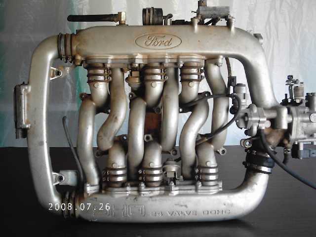
A lot of time has gone by, but progress continues slowly. Here is the pre-assembly of the famous SHO Intake Manifold. I've been taking my time making sure everything is fitting together properly.

(Here are two pics. For some reason the yellow gets washed out in the sun)


It will be some time before this goes on the engine as I have to clean, lengthen & rewrap the engine wiring harness before the intake manifold can go on. The harness sits down inside the middle of the valve covers under the intake.

Sunday, November 16, 2008

Engine Art - continued . . .


Well, as my engine assembly continues, the Art is taking form. It will still be some time before we get to see if the function follows as closely to the form as intended. But I remain optimistic.

The yellow and red colors will correspond to the split-color bumpers - front & rear. The cars overall color is Signal Orange. The split-color bumpers were used on the factory GT cars to aid in identifying them on the track. Though this will be far from a factory-like car, I still like the concept.

Saturday, August 2, 2008

Mechanics of Art

Nothing too exciting going on this weekend - just continuing to work on the project. I've been working on the intake manifold (described previously) removing flanges and grinding and reshaping. Still have a couple left to finish.

I spent this morning removing the casting/forging seams from the intake runners - the snake-like tubes on the intake manifold. These seams are produced by the mating of the two halves of the form dies used to make the part. They're not that noticeable or pronounced, but since I was going for a more refined look - it only made sense that I should take this extra step.

Here's an example of a before and after.


Something similar will be done to smooth out the inside of the runners to improve the air flow by a process called extrude honing. Attention to the outside is the form & attention to the inside is the function.

Wednesday, July 30, 2008

Engine Parts - Art?

Here are some additional examples of manifolds that have been painted and beautified by other SHO owners . . .


Purty aren't they?

Monday, July 28, 2008

Porsche Project - Engine parts

Since I have a progress thread for my Porsche project it doesn't make much sense to duplicate my postings here, so I will note some highlights with links to the latest changes. The last couple of days have involved cleaning and prep for painting the SHO intake manifold and valve covers.

The intake manifold is quite large and there are numerous attachments that I will not be using on this car so the bosses where these mount can be removed. This should make the already beautiful intake manifold all the more attractive.


Some are certain that only a gear-head could appreciate the beauty of something so mechanical, but I've never been accused of being, or consider myself, a gear-head. The beauty for me lies not only in the form but also in the function.


By modifying it I'll be removing some of the eccentricities and restoring some of the basic symmetry of the design. Plus it will get a nice dose of color to tie it into the overall theme.


See the 3D914 Project ink on the right for the latest posting.